

|
Second Generation SpecificationsThe first generation fracturing tool proved that the throughput was sufficient and that the fractured output accurately represented the input data. Now we have been requested to add features and additional data inputs. Additional Data FormatsIn addition to GDSII, the second generation fracture engine should read RS247X (Gerber) and ODB++. Both formats are produced by the great majority of PCB layout tools. 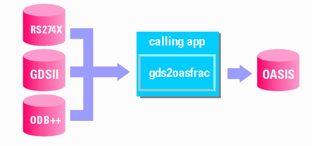
User Control of Tile OrderingDepending on the "physics" of the image writer the order that the tiles are available is important. The fracture software should offer several different ways of ordering the tile data. Since all the tile orderings begin with the upper left tile, we will always name that one tile1_1. Tile Direction 1 Starts at the upper left of the array, runs downward to the bottom, shifts over to the right one column and repeats. 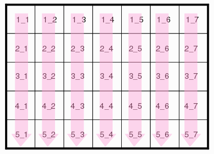 Tile Direction 2 Starts at the upper left of the array, runs to the right, shifts down one row and starts again at the left. 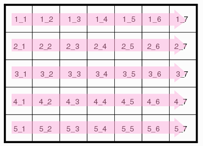 Tile Direction 3 Starts at the upper left of the array, runs down the column, shifts over one column and runs up in the opposite direction. This is known as a "serpentine" path. 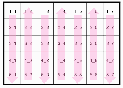 Tile order 4 starts at the upper left of the array, runs to the right across the row, shifts down one row and runs across in the opposite direction. This is known as a "serpentine" path. 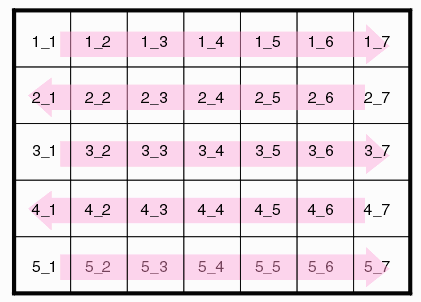 How Tile Order Direction Affects the Data Base InternalsThe tile order requirement affects how the tile data is written to the output file. Assume we have the layout and tiles shown in the above illustrations. How do these show up in the actual OASIS database? In the table below, the DEFNSTR indicates a structure or cell definition. The tile structures contain only geometry entries. After all the tiles have been defined, a top level structure inserts each one in the correct X,Y position using an SREF command.
Identifying Cell Locations in the FileIf the end user's rasterizer needs to quickly access a cell's contents it is most helpful to be able to lookup the location in the file from a table. This is especially true when there are many rasterizers working on a single OASIS file, each processing an independent cell/tile. A table should be created that correlates each cell name with its first byte: Cell Byte Offset from beginning of File DEFNSTR TILE1_1 OO5A4B0 DEFNSTR TILE1_2 OO5A6B0 DEFNSTR TILE1_3 OO5B4B0 DEFNSTR TILE1_4 OO5C4B0 DEFNSTR TILE1_5 OO6A4B0 DEFNSTR TILE1_6 OO7B4B0 DEFNSTR TILE1_7 OO5A4B0 DEFNSTR TILE2_7 OO5A4B0 DEFNSTR TILE2_6 OO5A4B0 DEFNSTR TILE2_5 OO5A4B0 DEFNSTR TILE2_4 OO5A4B0 DEFNSTR TILE2_3 OO5A4B0 DEFNSTR TILE2_2 OO5A4B0 Tile OverlapThe user may require that the tiles have a certain amount of overlap. The user would like to be able to specify separate overlaps in X and in Y. For example, consider the case shown below where the tiles are not overlapped and the golden corner is in the upper left. 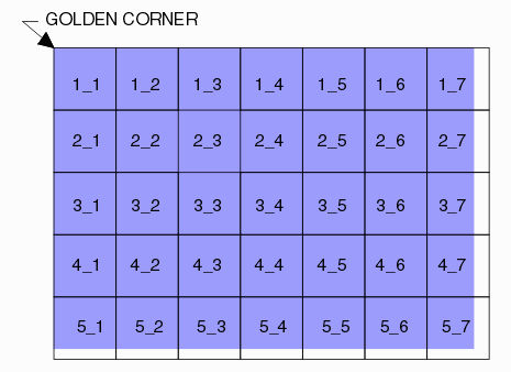 An overlap value for both X and Y can be specified. The center of each tile is not affected. Every tile's extents are increased by 1/2 of the overlap value as shown below. 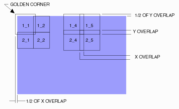 Output Grid Snap The user can specify an output grid and fractured data will be snapped to the specified grid. OASIS native grid is 0.001 um (1 nm) but the user can specify a coarser grid such as 0.01 um if needed. However the selected grid snap must be a multiple of 1 nm so a snap such as 2.5 nm is not possible. Mask IDThe maskwriter OEM may wish to label the masks to help identify them. 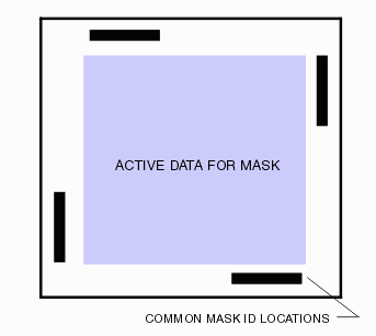 This function is done by entering: a) string of text b) text height c) text justification mode (lower left, middle center) e) text insertion coordinates f) rotation g) mirroring The actual font used should be specified by the maskwriter OEM. It is likely to be an OCR style font.  |