
|
SizingThe sizing of polygons (especially in a mask environment is fraught with potential problems especially when dealing with non-Manhattan data. How corners are dealt with can greatly affect the usefulenss of the final results. Bool.dll has a considerable number of parameters that control the sizing behavior. Which Functions Control Sizing? Control of Sizing is spread between several different functions: |
|
enables the user to set which mode of sizing to use: none, standard, isotropic (sizing is the same in X,Y) and non-isotropic (sizing differs in X,Y) |
|||
|
sets the value of sizing for isotropic sizing. This may be a negative or positive value. |
|||
|
controls how many vertices are used to approximate a radiused corner - 3 or 5. For standard sizing, which does not attempt to miter the corners, this parameter has no effect. |
|||
|
enables the user to set which mode of sizing to use: none, standard, isotropic (size is the same in X,Y) and non-isotropic (sizing differs in X,Y) |
Sizing ModesThe function, QisBoolOptions_SetSizingMode, controls which sizing mode (if any) is used. The Standard mode is our original sizing algorithm but we don't recommend using it anymore since the Isotropic mode is more robust for corner cases. The non-isotropic mode is used only when the sizing in X and in Y are not the same. 
|
Round CornersThe function, QisBoolOptions_SetRoundCorners, controls how corners are handled assuming the mode selected is isotropic or non-isotropic. If all your input data is Manhattan, then use the RightAngle parameter for round corners. If your data is all angle such as RF/microwave circuitry, and there are acute angles in your polygons then 3 or 5 point will prevent the acute angled corners from growing excessively. 

|
Small FeaturesFor many applications the amount of sizing is much smaller than the geometry features. However there are cases where the sizing amount and the smallest features in the geometry are similar. This can cause some features to actually disappear.  |
|
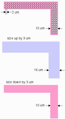
Removing Holes with Small Feature We actually used this as a feature for one application where the wide metal power line had cheese grater holes cut into it in order to keep the metal density under control. However this was causing havoc for a EM field simulator. We were able to remove the holes from a very large IC database by sizing up and then down again as shown at right. top - a 10 um wide power line with 2 x 2 um holes cut into it (re-entrant polygon) middle - sizing up by 3 um causes the holes to "collapse" upon themselves. bottom - sizing back down by 3 um and the original width of the line is restored and the holes are gone. |

|
| Documentation | Download | Price | Revision History |