

|
The PBGA1 ExampleIn this example we take you through converting a simple 2 layer PBGA with one layer of wires. We first take the user through the example using the Windows GUI and then a second time on how to run this from a command line and resource files (for those wishing to call NETEX-G from their own application.) Our objective is to generate a GDSII stream file that is organized by net/layer. Wires will be treated as paths in GDSII starting at coordinate where the die pad is located. The other end of the wire will terminate above the bond finger and a small via will be located under the wire to connect from the wire layer to the metal layer holding the bond finger. |
||
|
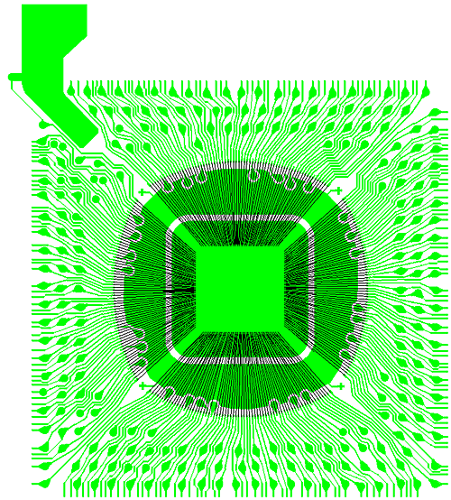
At right you can see a simple two layer laminate BGA. In addition to Gerber files for the top and bottom metal, there is also an Excellon drill for the vias and a Gerber file for the wires. The NETEX-G crossection is shown below: 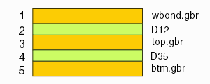 How the stackup is defined in NETEX-G depends to some extent on the target output. For output such as GDSII one must insert a dielectric between the wires and the top layer of metal. For output to Ansoft no such dielectric is needed since the Ansoft SI tools recognize that the wire floats free above the metal. |
|
|
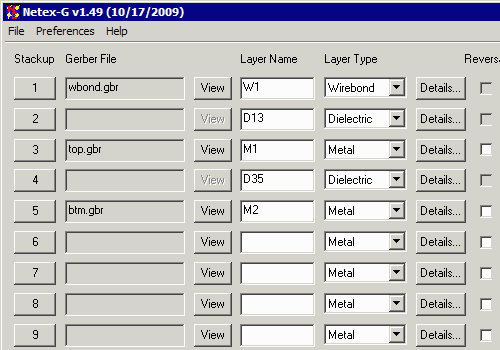
Placing the Gerber LayersTo extract the nets from the Gerber data start up NETEX-G. You will be presented with the layer stackup dialog. Select the correct Gerber file for each layer starting at the top of the stackup and working down. Since our target output is GDSII we need a dielectric between the wire layer (which has no special meaning in GDSII) and the top metal layer. |
|
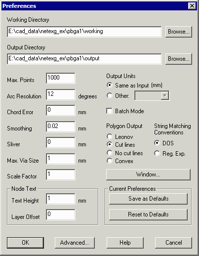
Preference SetttingsBefore running NETEX-G check your preference settings. | ||
|
Working Directory -- all temporary files generated by NETEX-G will be written to this directory. It is useful to isolate them in one place away from the input/output files so that they can be easily deleted once the job is complete. Max Points -- max number of vertices per output polygon. If exceeded, the program breaks the polygon into two (or more) less complex ones. In this example it has been set to 1000 vertices but can be set lower or higher depending on the target system. Arc Resolution -- parameter to convert arcs into segments. Values range from 2 degrees to 30 degrees. Larger values generate coarser arc approximations but run much faster. Chord Error -- parameter to convert arcs into segments. This value is the max difference between the ideal arc and the approximation chord. Chord error uses more segments for large arc radii and less for smaller arcs. |
|
|
Smoothing -- smoothing is a routine that reduces the vertex count after booleanization by removing closely space vertices. The parameter shown here, 0.02 mm will remove a vertex if a neighbor is within 0.02 mm of it. |
Sliver -- removes tiny slivers of isolated metal that are generated due to arc approximations and the boolean process. |
|
|
Max Via Size -- prevents NETEX-G from assuming that large round pads are vias. Set this value slightly larger than the diameter of the maximum via you expect to use in the conversion. |
Scale -- scales output data as needed. Default=1. |
|
|
Polygon Output -- for GDSII only Cut Lines or No Cut Lines is acceptable. GDSII does not recognize Leonov polygons. Other outputs such as ASCII and ANF do support Leonov polygons. |
Output Units -- by default the output units match the Gerber units (mm or inch) For some output formats such as GDSII units such as microns are preferred. The output units can be modified using this option. |
Drill Data to ViasThe vias that connect the various layers are defined by one or more files that generally come from the drill file created for manufacturing. The drill file must first be converted into a Gerber file using the drill2gbr utility. The resulting Gerber file is then loaded into the drill section so that the NETEX-G program can generate vias between the layers. All types of vias are supported: through hole, blind and buried. It can sometimes be difficult to convert a drill file to the approriate Gerber file because drill files don't always contain in their header a full description of the file's contents. Therefore the user has to enter this information and knowing what to enter can be problematic unless you are quite familiar with the data formats. Discussing how best to choose the parameters is not covered in the scope of this document. |
|
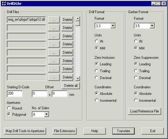
The dialog that controls the conversion of the drill file (pbga12.drl) into a Gerber file (pbga12.gbr) is shown at right. First we load one of the Gerber files in the stackup as a reference. This will extract the data format, mode and zero suppression from the Gerber data. The user has to manually enter those same parameters for the drill data as they cannot be extracted automatically. Notice that since we are going to GDSII, I have set the aperture to be a polygon with 8 sides. This will reduce the GDSII file size. |
|
|
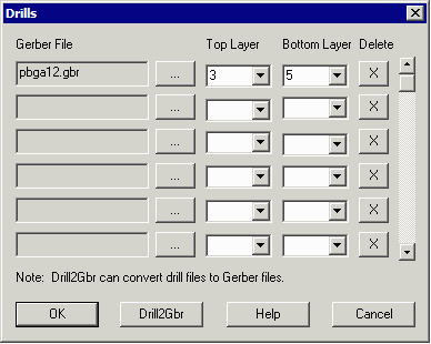
The file drill.gbr contains the via holes between the top metal and bottom metal. If you examine the stackup this means that the drills run from stackup layer 3 to stackup layer 5. |
|
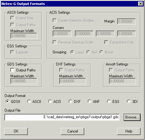
Output DialogNetex-G has many possible outputs so it is necessary to define the output and any "flavoring." GDSII has no special flavoring options so we just have to specify the output filename and directory. |
|
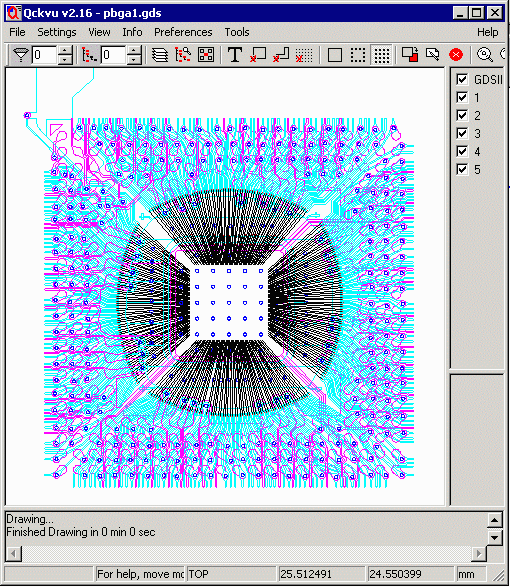
GDSII OutputThe output produced by NETEX-G for this example is a GDSII stream file. The GDSII file has a layer for each stackup. The screen shot at right uses Artwork's Qckvu to display the stream file. |
|
|
|
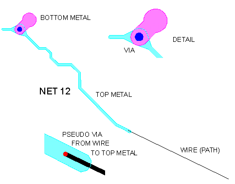
GDSII File Organization Each set of connected conductors (a net) is grouped in its own structure. This enables the designer to view each net individually. In the illustration below the user has selected NET12 from Qckvu's structure navigator. NET12 contains a wire, a via to the top metal, top metal, a via to the bottom metal and bottom metal. |
|
|
Page 2 - Getting the Same Results from a Command Line .... |