Running the PBGA1 Example with ANF Output

This example uses the same PBGA but shows the differences in setup when writing to Ansoft's ANF format. The major changes include:

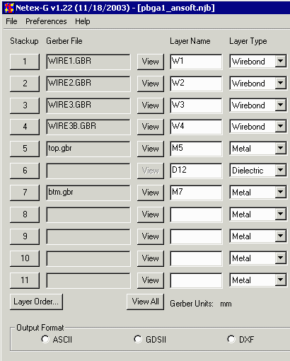
    Wires separated into multiple layers - Instead of all of the wires grouped in a single Gerber file there are now 4 separate Gerber files each containing a subset of the wires. The grouping was based on wire loop height parameters which ANF will simulate. For example, WIRE1.GBR contains all of the wires that go from the outer row of die pads to the VSS ring. WIRE2.GBR contains all of the wires that go from the outer row of die pads to the VCC ring. Because this design is staggered, the wires that go to the bond fingers have been separated into two groups WIRE3.GBR and WIRE3B.GBR depending on whether the wire originates from the outer or inner row of die pads.

    Padstack for Solder Balls - In order to use the ANF results in a program such as HFSS or Spicelink 3D one needs in the ANF file a padstack to which solder balls can be attached. The solder balls act as one "end" of the net to be analyzed. Since NETEX-G booleanizes the input Gerber data it does not retain any padstack info. Instead we created the padstacks using a fake drill that starts/ends on the bottom layer.

    No dielectric needed between wire layers or wire/metal layers - the Ansoft tools recognize wires as a special entity and when building up the stackup it is not necessary to insert a dielectric between wire layers nor a dielectric between a wire layer and the metal layer below it.

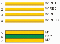
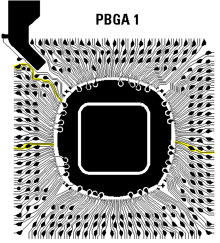
This is a simple 2 layer laminate BGA. In addition to Gerber files for the top and bottom metal, there is also a Gerber file for the vias and a set of Gerber files for the wires. The NETEX-G crossection is shown below:
pbga crossection

The stackup shown above is set for Ansoft's Neutral File (ANF output)
pbga 1 top layer


Layer Stackup
ANF

To extract the nets from the Gerber data start up NETEX-G. You will be presented with the layer stackup dialog. Select the correct Gerber file for each layer starting at the top of the stackup and working down. Since our target output is ANF we do not need a dielectric between the wire layers and the top metal layer.

layer stackup


Preference Setttings

preferences

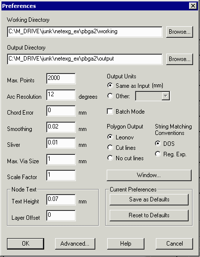
Before running NETEX-G check your preference settings.

Working Directory -- all temporary files generated by NETEX-G will be written to this directory. It is useful to isolate them in one place away from the input/output files so that they can be easily deleted once the job is complete.

Max Points -- max number of vertices per output polygon. If exceeded, the program breaks the polygon into two (or more) less complex ones. In this example it has been set to 2000 vertices.

Arc Resolution -- parameter to convert arcs into segments. Values range from 2 degrees to 30 degrees. Larger values generate coarser arc approximations but run much faster.

Chord Error -- parameter to convert arcs into segments. This value is the max difference between the ideal arc and the approximation chord. Chord error uses more segments for large arc radii and less for smaller arcs.


Smoothing -- smoothing is a routine that reduces the vertex count after booleanization by removing closely space vertices. The parameter shown here, 0.02 mm will remove a vertex if a neighbor is within 0.02 mm of it.


Sliver -- removes tiny slivers of isolated metal that are generated due to arc approximations and the boolean process.

Max Via Size -- prevents NETEX-G from assuming that large round pads are vias. Set this value slightly larger than the diameter of the maximum via you expect to use in the conversion.


Scale -- scales output data as needed. Default=1.

Polygon Output -- for ANF output select Leonov polygons.


Output Units -- by default the output units match the Gerber units (mm or inch) For some output formats such as GDSII units such as microns are preferred. The output units can be modified using this option.


Drill Data to Vias

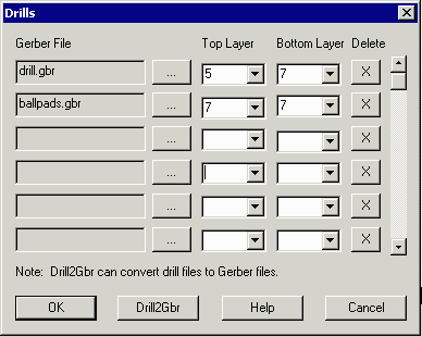
The vias that connect the metal layers vertically are defined by one or more files that generally come from the drill file created for manufacturing. The drill file is first converted toa Gerber file (using our drill2gbr utility) and then loaded into NETEX-G as shown below. All types of vias are supported: through hole, blind and buried.

A drill that starts/ends on the same conductor layer places a "fake" via on that layer with an associated padstack. This is what is needed for ANF to attach a solder ball to the bottom of the package. The Gerber file ballpads.gbr serves this purpose. The file drill.gbr contains the via holes between the top metal and bottom metal. If you examine the stackup this means that the drills run from stackup layer 5 to stackup layer 7.

drill dialog

Select an output file name and save the job file (the job file contains all of your settings and can be reloaded later to run this job again ...). Now execute NETEX-G. Extracting all the nets and converting to ANF should take less than a minute.

Results

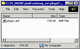
When the extraction is complete an ANF file should reside in the output directory:

If you would like to view the ANF file yourself, you can download it from here:

pbga1.anf.zip 182 KB.
ANF output file


ANF Output

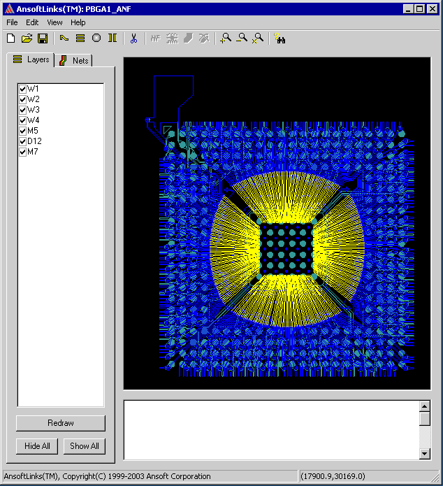
The output produced by NETEX-G for this example is an Ansoft Neutral File. stream file. The screen shot below uses Ansoft's ALINKS program to display the layout. The user would select the desired nets in ALINKS, set the wirebond parameters and attach the solder balls. After doing this the results are exported to formats supported by SpiceLink, HFSS or Turbo Package Analyzer.

ANF File displayed in ALINKS 2.5


Back to Benchmark Page