Calculating a Proximity Net
If you are using NETEX-G to extract the conductors for a net or nets and you plan to use the data to create a SPICE equivalent model of the layout, then you will also be interested in nearby conductors/nets that capacitively couple to your selected nets. We call these proximity nets.

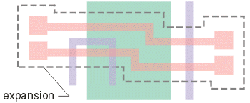
the two pink nets are the ones to analyze. Other conductors (even on other layers)
will influence the capacitive coupling.
NETEX-G can grab all such conductors if instructed to do so. It then aggregates all of those into a single group we call the "proximity net". Your 3D field solver can then "ground" the proximity net in order to calculate the fringing capacitance.
To direct NETEX to calculate a proximity net you must do two things:
use the -couplings option on the netexmgr command line.
netexmgr test.gds TOP -couplings -cfg:test.cfg
specify an non-zero value for the expansion distance in the netex configuration file.
EXPANSION 5.0
How it Works
- NETEX does an extraction of all nets.
- NETEX finds your selected nets (either by coordinate or by name.)
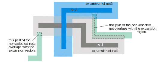
- NETEX sizes up the area of each of the selected net(s) using the expansion distance.
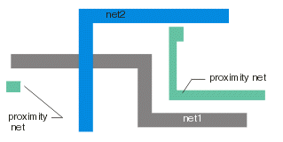
- NETEX then finds any non-selected nets that intersect with the expansion region, clips to the edge of the expansion region, and stores all pieces in the "proximity net".
The illustration below shows this in detail. NET1 (dark grey) and NET2 (dark blue) are the ones selected for analysis.
|


