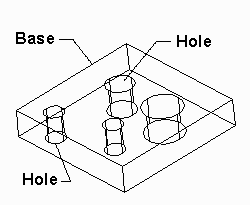
One might think that generating the drill hole locations from a simple 3D STL file (say consisting of a plane with different sized holes drilled into it) would be simple -- but one would be very wrong.
Though the hole you define in your 3D modeling software may be a well defined entity, by the time it gets to the STL format it is merely an empty region surrounded by triangular facets. Its "holeness" is lost.

However, with some work we can usually recover the holes and thus can generate drill data for the PCB manufacturer.
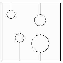
The first step is to "slice" the board at some Z value. This gives us our 2 dimensional layout as shown at right. The polygons use "cut lines" to surround the holes. However we still have a single complex figure and no data on the hole center or diameter.

Cut lines surround holes.
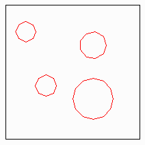
With the proper geometric manipulation one can represent the same data using embedded polygons instead of cutlines.
The first layer (or embedding level) is the rectangle surrounding the holes. The holes belong to the second layer or embedding level (shown in red). Now we've got distinct entities for the holes.

embedded polygons.
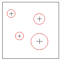
The final step is to use a pattern recognition routine that analyzes each polygon and determines whether or not it looks close enough to a circle to convert it to a circle. We normally require 20 sides or more and a certain uniformity in the length of different sides.
Once we have the various diameters we can find the unique diameters, generate a unique flash for each diameter and output a round flash for each hole. This is exactly what is needed to generate drill data.

flashes w center/diameter