3D Via Modeling
For detailed PCB simulation it may be necessary to properly model vias. There is always the trade-off between accuracy and the size of the problem and numerous vias will contribute to size issues. So the goal is to keep the data manageable while creating a model that is accurate enough.
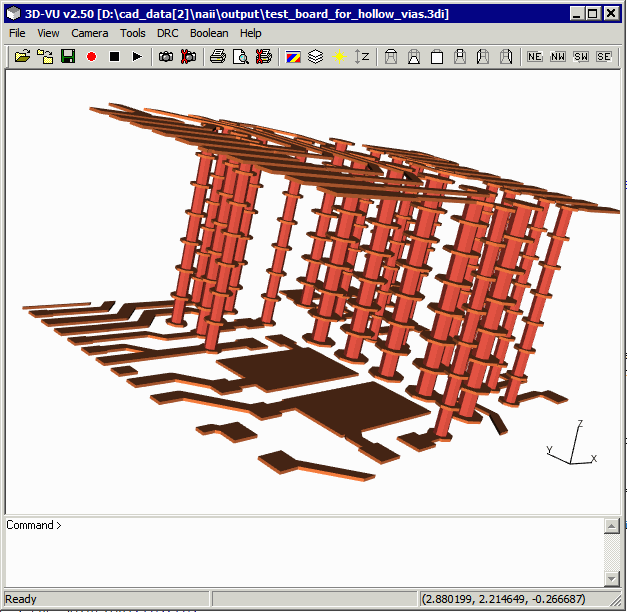
When the vias are first generated from the PCB data they are built on a per-layer basis. So you end up with a stack of cylinders -- the diameter corresponding to the drill diameter -- that connect the conductor layer above and below each section.

The vias are actually represented in the 3Di format as circles with a center point, diameter and start/end layer. There is a parameter indicating the number of sides which is used for rendering purposes. The 3Di database also assigns the via body an ID -- and it is smart enough to assign the same ID to all the cylinders at the different Z levels.
Reducing Face Count
This 3D mode, once converted into solid bodies, is not very good for FEA. It generates a lot of un-needed faces which bog down the mesher and the simulation.
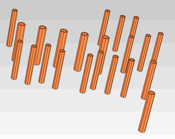
The obvious solution is to combine all the vertically stacked members into a single "tall" cylinder which is what 3Di2STEP does when you select the option: Merge Via Parts with the Same ID.

Via columns constructed from stacks of cylinders
Drilling Holes in the Conductors/Dielectric Bodies
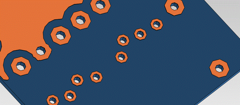
However doing this forces us to do another set of operations. We can't have the via cylinder colliding or interfering either with the conductor bodies it passes through or the dielectric bodies. So we need to "drill" out perfectly matching holes in all those bodies.

Solid or Hollow?
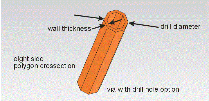
How do you want your via modeled? As a solid cylinder or as a hollow one? The hollow one might be more representative of the board reality but it will also generate more faces to mesh and simulate. To get the hollow model select: Add Drill Holes to Vias with diameter XXX. You will then specify the wall thickness.

Solder Plug?
Vias are often filled in with solder - a softer and different material that the copper used to plate the wall. If you want 3Di2STEP to generate a "plug" in the hollow via model then click on: Add via plugs to fill via drill holes ...
