whats_new_logo.gif

June 2005      

Here is a quick summary of various products and ideas Artwork has been working on during the last year. If any of these are of interest, please contact us.

Table of Contents

  QIS   How over three years, QIS evolved from a image server into a general purpose OEM engine for large GDSII files ...

  NetTrace   how to identify and trace nets (in real time) with just a GDSII file as the input data ...

  OASIS   the next generation GDSII replacement has arrived intended to shrink those 50GB GDSII files down to 1GB. Are you ready yet?

  Polygon De-Embedding   tired of editing and redrawing those those pesky AutoCAD derived masks that haven't been drawn "correctly...

  STL2GDS   3D MEMS design are often done using software that can't produce Gerber or GDSII. STL2GDS slices a 3D body to produce 2D GDSII/Gerber mask data...


QIS (Qckvu Image Server)

Much more than just a GDSII image server.

Back in 2002 when we started work on QIS (Qckvu Image Server) we envisioned it as a way to develop WEB based viewers for large GDSII files. QIS would open the file on a powerful server, zoom in as instructed and return a bitmap of the window under inspection. A lightweight Java based client would handle the display on a PC or any other machine equipped with a WEB browser. (think of MapQuest but for IC mask data ...)
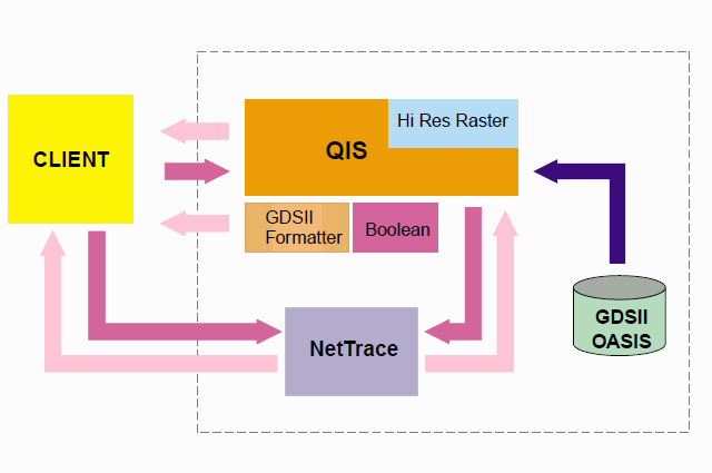
QIS Flow Chart and Modules

But that’s not how our customers saw it. The early adopters of QIS used it to drive their own GDSII viewers and data processors. QIS does the heavy lifting and the client software handled the display of bitmaps. We now have seven OEM users of QIS including: Synopsys, KLA Tencor, Applied Materials, Lite Enterprises, Credence, Fujitsu and Hitachi.

Boundaries and Paths are Nice ...

We added a vector (i.e. boundary/path) output to QIS which our customers found could be used to extract small regions from very large files for all types of analysis -- especially lithography simulation which takes so much computation that it is only run on a few critical areas. QIS made it easy to find these regions, get the geometries and start up the simulator.

Can I clip that for you?

Once we added the ability to extract all the polygons that crossed a given window one of our customers then asked -- “Could ya clip those polygons at the window boundary?” “Sure”, we said and added a boolean module to QIS. Of course, you can save the clipped region to a new GDSII file.

High Res Rasterizer

QIS had a built in rasterizer but because it was designed to drive a display screen it was limited to about 3000 x 3000 pixels. A company building wafer & mask inspection equipment needed a high resolution rasterizer that could produce 10,000 x 10,000 pixel images in order to compare the CAD data against windows acquired by the inspection cameras.We added a separate high resolution rasterizer and now several inspection machines have QIS embedded into their control software.

Push a few Polygons Around

Then a customer asked, “I just want to add and subtract a few polygons, and maybe I could create a new cell to hold them?” OK, we said and added basic editing functions to QIS.

Can I Get That in Linux?

Initially we figured QIS would run mostly on big Sun workstations. But then Linux showed up and AMD’s 64 bit Opteron chip did too.We soon released QIS running on 64 bit Opterons and recently added 64 bit Xeon’s and Pentiums under Suse 9.3

The Ankle Bone is Connected to the Knee Bone ..

“Gee, wouldn’t it be great if I could click on a polygon and see what is connected to it?” said one of our customers. “Sure” we said and then figured out that this is pretty tough to do on large files with a billion polygons. But that’s exactly what we are working on now. See the article on NetTrace for details ...
 

NetTrace

the knee bone is connected to the ankle bone ...

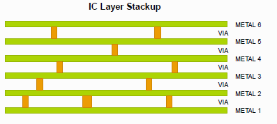
Sometimes you desparately need to know how to get from point A to point B. This applies to nets on an IC chip as well as to freeways in Southern California. The problem you face when viewing a large GDSII file is that a net travels on conductors running along anywhere from four to six layers of metal and it pops up and down between layers through terribly tiny vias. Trying to trace from point A to point B manually is just about impossible.

crossection of a typical 6 metal layer IC.

Wouldn’t you like to click on point A and see everything connected to it light up? That would make it real easy to see if point A and point B are connected.

NetTrace is designed to do just that: Click on a point (inside a conductor, of course) and “immediately” everything connected lights up.

How does it work?

Starting on the polygon you selected, NetTrace grabs all other conductors that touch or overlap the selected one. This process is repeated until everything on the starting layer connected to your source point is collected.

Next, NetTrace has to look at the layer above and below the start layer; assuming that these are via layers it finds vias that touch or overlap the collected polygons. NetTrace jumps to the new layers and collects everything touching the connecting vias.

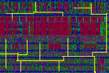
This process is repeated until everything that connects through vias or by touching has been collected. Once you have such a colllection it is easy to highlight those items.

highlighted net

It’s not quite that easy!

Like everything else, the devil is in the details. In this case the devilish details are speed and size. As users, we want net highlighting to be instantaneous; yet we deal with enormous files -- as the late astronomer Carl Sagan was fond of saying -- billions and billions of polygons.

Some of the same techniques used to speed up panning and zooming in the GDSII viewer help us out here. The QIS viewer has already built a quad-tree that sorts the polgyons and cells into windows. The NetTrace engine can ask the viewing engine for a small set of polygons that it knows are in a particular window. The computations needed to determine touching are sensitive to the number of polygons under consideration -- by keeping the set small, the computations go quickly.

Artwork’s Implementation

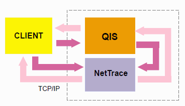
Because the speed of net tracing relies so much on the same computations used to build a fast viewer, we developed NetTrace as a module that talks directly to our QIS image server.

The client communicates with QIS and NetTrace via TCP/IP NetTrace talks to QIS via shared memory.


OASIS

Next Generation GDSII?

OASIS is not an 80’s rock band. It is the name of a new data format intended to replace the venerable GDSII stream file format.

Why? - GDSII was defined in the early 1980’s -- remember the days when programs ran in 64K of RAM? When a house in Silicon Valley cost $50,000? When a 5MB hard drive cost $500? No? Well no one imagined then that 20 years later there would be IC’s with a billion polygons in them. Or chip designs with 500,000 structure definitions.

GDSII files are getting too big to handle gracefully and the problem is getting worse month by month. A group of prominent parties got together a couple of years ago and defined a new architecture that would represent the data much more compactly and efficiently.

The Details

OASIS retains GDSII’s structure and form but includes:

    more polygon “styles” optimized for for low byte count by taking advantage of the fact that most polygons are small and can use a double byte anchor point and single byte deltas for the height and width.

    Built in Z_lib compression (within a cell definition only) So there is no need or point to compress and decompress OASIS files.

    More Layers, More Vertices and Longer Structure Names -- a good thing, right?

    Array and Repetition Commands for Entities -- very useful for certain types of files; especially GDSII that has been run through optical proximity correction.

    Modal data -- once a parameter has been set its value is retained until changed. For example, once you have defined a layer, you don’t need to repeat the layer value for each susbsequent entity until you change to a new layer.

Advantages

    A 50GB GDSII file is likely to be a 1GB OASIS file. Not that there is any less actual data; it’s just packed tighter. This makes moving around the data a whole lot easier.

    Disk I/O is also greatly reduced when reading and writing OASIS.

Minuses?

My grandfather always said, “There’s no free sandwich” and the same applies here. While OASIS is very efficient in storing data, writing OASIS is difficult. Every CAD tool that once wrote GDSII must be updated to write OASIS. This won’t happen anytime soon. Some CAD tools will write poorly compacted OASIS and others will inevitably write illegal OASIS; the more complicated a format, the more likely someone will mess it up.

IC designers write lots of custom code to crunch their data and much of this code reads and writes GDSII. Either OASIS data has to be converted to GDSII first to run through these utilities or the utilities have to be rewritten to support OASIS. The authors of lots of these utilities have long ago moved on so this will be a major stumbling block.

Finally, reading and extracting data from a very tightly packed OASIS file is compute intensive -- as developers of a OASIS viewer we find there is a high overhead to decompress data on-the-fly and to handle commands like modal variables. One can’t easily poke directly into the compressed sections of an OASIS file; decompressing data and storing on disk spends the savings in IO operations and disk space.

Adoption?

How fast will OASIS be adopted? This is anyone’s guess. Some very important tools such as the CATs fracturing engine now read OASIS so the photomask and wafer foundries can probably accept it. But many tools that these foundries use may not run on OASIS. The jury is still out.

Artwork’s Product Plans

We’re using QIS as the vehicle to read and write OASIS. The first step is just to be able to read the database and to write it out without taking advantage of compression, optimal polygon choice, modal variables or repetition. This step is complete.

Next, we will work on accelerating the scanning and decompression of the data and will try to keep disk I/O and memory footprint to a minimum. This will be a long term project.

Finally we will look at optimizing the writing of the database to take full advantage of all of the tricks available to make the file tight and efficient.


Polygon De-embedding

Who is in and who is out?

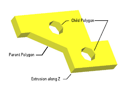
Some folks in the mechanical drafting world draw embedded polygons but really expect the polarity to change. Well when converting to GDSII the polarity didn’t change automatically and they didn’t get the expected mask.

Artwork’s de-embedding routines fix this with proper cut lines making life a lot easier. You know who you are.

cutlines generated by ASM 3500s de-embedding routine.

De-embedding is now available for ASM 3500 (AutoCAD DXF to GDSII ) and ASM 500 (AutoCAD DXF to Gerber)


STL2GDS

3D MEMs meets 2D IC Lithography

After 25 years we are finally seeing MEMs crawl out of the R&D basement and into everyday products. My new TV at home uses a T.I. DLP with 1 million tiny mirrors to drive the display. MEMs are designed using 3D mechanical software such as SolidWorks.

3D Body needs to be sliced along a z-plane to get a 2D GDSII mask layer.

MEMs are manufactured using IC processing and for that you need GDSII to drive the mask writer.

How do you get from 3D to GDSII?

There’s a handy database called STL developed years ago for rapid prototyping. Every 3D tool writes STL.

Artwork developed an STL2GDSII translator -- or rather a processor since we “slice” the STL body to produce one or more GDSII layers. We also have a STL to Gerber converter and are working on a GDSII to STL where the user specifies the thickness and layer stackup to go from 2D to 3D.