Data Transformations and Windowsing
InkRaster includes controls for windowing and data transformations.
Windowing
If no window is specified then the program scans the input data and computes the data extents. If the user wants to specify a specific window then the -window: argument should be used followed by the lower left X, lower left Y, upper right X and upper right Y corners in the same units as the input file (Gerber files are alway either in units of inches or mm)
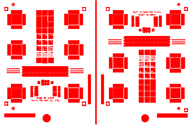
In the example shown below, the user wants to print only the circuit on the right hand side so defines a window containing only that region.

The -window: argument on the command line is:
-window:75,0,145,94
and the resulting bitmap will look like this:

Note that any transformation such as rotation, mirroring or scaling are done after the window selection has been made. Therefore one need not account for these transformation when computing the desired window.
Mirroring
InkRaster enables the user to mirror the data either around the X axis, the Y axis or both XY. The respective command line options are:-mirror:X mirror about the X axis -mirror:Y mirror about the Y axis -mirror:XY mirror about both X and Y
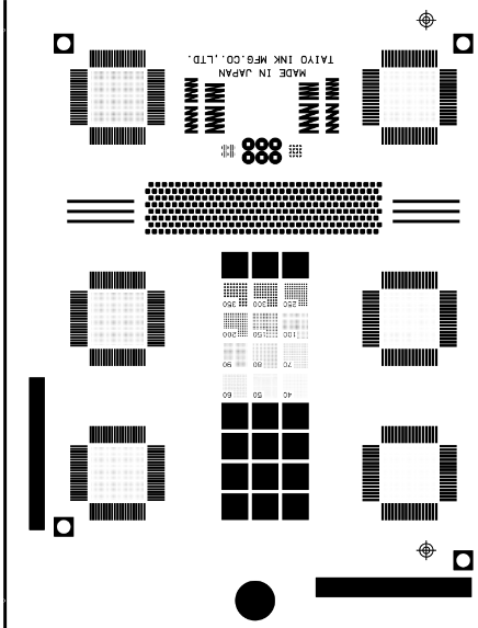
The illustration below shows the effect of the mirror transformation on a small section of demo2.gbr.

Rotations
Inkraster supports any angle rotations. Though most rotations are in increments of 90 degrees either to obtain correct bitmap order or to fit a rectangular layout onto the table, it is possible to introduce very small rotations to support compensation for head alignment or other reasons.
The following illustration shows the results from first windowing our a small section of demo2.gbr and then applying a rotation. The size of the bitmap is obviously computed after the rotation.

Scaling
InkRaster supports scaling -- and more importantly -- it can scale in X and Y independently. Different scales in X and Y are often used to compensate for slight "stretching" of the substrate due to thermal or processing it passes through and it needed to improve the registration of the printed features with existing features already printed, drilled or etched into the substrate.
Very small values of scaling are supported such as 1.0005. However in the illustrations below we have used large scale values so the effect is clearly visible.
-scale:1.0
-scale:1.0,1.2
-scale:1.3,1.0
-scale:0.9,1.1

Margins
Sometimes the bitmap should include empty margins as required by the printing equipment. The -margin argument can be used to add such margins. Margins can be specified either in the input units (i.e. mm or inch depending on the units of the Gerber file) or they can be specified in pixels.
-margins:12.5   (12.5 mm assuming input Gerber is in mm)
-margins:1250px  (1250 pixels)
Margins are applied after all of the vector transformations such as scaling, rotation and mirroring.
Order of Transformation
The transformations are performed in this order:
Window - either the user defined window or the data extents.
Mirror - any mirror commands are processed next.
Rotation - any rotation is then applied
Scaling - scale factors are then applied
Margins - if margins are specified they are applied last.
