 |
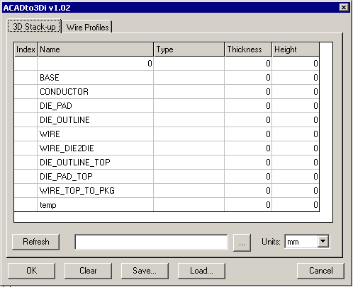
Defining the Layer StackupSince our AutoCAD drawing is in 2D, we need to assign each layer a position in the stackup and also assign it a thickness. This is done using the 3D Stackup Tab in ACADto3Di's main dialog. Initially the stackup dialog will be empty - only a list of the layers in the drawing are shown. The index indicates where the layer lies in the stackup (more than one AutoCAD layer can share the same index number.) The Type is used to assign properties to the entities on that layer. The thickness represents the Z extrusion height of entities on that layer. The height is computed by the program. |

|
|
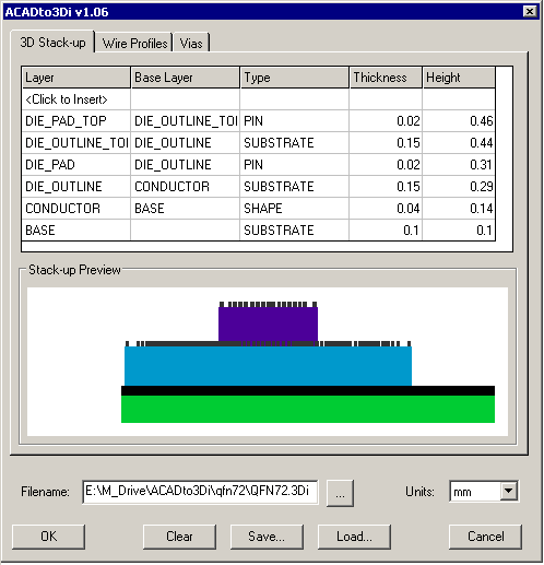
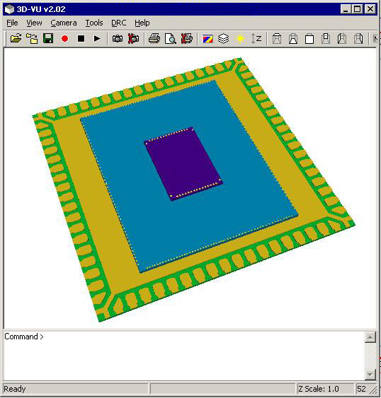
Our Stackup Let's assign stackup positions to each layer starting at the "base". Some reasonable values will be assigned as thickness. But let's ignore the wire layers and just make sure our substrate and die bodies are OK. Here are the values entered. Notice that the DIE_PAD layer and the DIE_OUTLINE_TOP both have both sit on the DIE_OUTLINE. If we export to 3Di and then view the results using 3DVU it will look like the image below: |

|

|
|
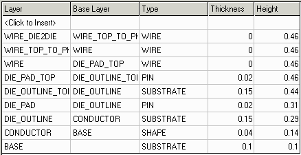
Wire Layers It actually does not matter where in the stackup you put the wire layers, but by convention we always put them at the top. This is because we need to use the Wire Tab to control where the wires start and where they land and what profile they will have. Let's do that next. First we'll add the wire layers to the stackup and then switch to the Wire tab. Continued on Page 4 ... |

|
| More Info 1 | 2 | 3 | 4 | |
| Drawing Rules | Examples | Download | Price | Revision History |
|
|