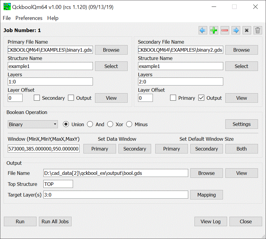

QckBool is controlled from a large dialog box as seen below.

New Session - starts a new session
Open Session - opens a previously saved session
Save Session - saves the current session for re-use later
Exit - closes the program
Global Preferences - Opens the global preferences dialog.
Help - opens a help file (HTML format)
QisMlib Report - reports which extensions are loaded.
About - reports the version, license and link to Artwork
Each set of inputs (file, structure, layers) and operation (unary, binary, Union, And, Xor, Minus) and output file along with the data window and any layer mapping is considered a job.
The user can define many jobs if desired. The user can then choose to run all jobs or a selected job. The directives consisting of a job are saved if the session is saved.
Navigating Through Multiple Jobs
Once the user has defined more than one job, it is possible to navigate between jobs using the icons shown below:

The icons mean (in order from left to right):
Move to Previous Job
Add a New Job
Remove Current Job
Move to Next Job
Reset/Clear Current Job
Delete All Jobs
For Unary Boolean operations there is only a primary file. For Binary Boolean operations (i.e. two separate inputs) there is both a primary and a secondary input.
For each of the input files, there is also an associated structure and one (or more) layers. These are also called the operands of the Boolean operation.
If you have only a single GDSII input file but want to perform an Binary operation such as XOR between layer 1 and layer 2 then set up a Binary operation. Both primary and secondary files will be the same (and use the same structure) but the layer listed in the primary will be 1 and the layer listed in the secondary will be 2.
You can specify a list of layers (comma separated e.g. 5,6,7) and if you need datatype discrimination you can use the L:D syntax for layer:datatype (e.g. 30:0,30:20).
Layer Offset - the layer offset is used for the viewer so that if your output layers or secondary layers are the same as the primary layers, you can offset layers in order to easily determine where the data originated.

We divide the operations into Unary (single input file), Binary (two input files; though they may be the same file), Sequential (a number of operations each following the other in a sequence) and Single Layer Mode (where layers are processed separately)
Union - all the polygons in the primary (layers are merged) are unionized so that there are no overlapping or touching polygons.
Reversal - all the polygons in the primary (layers are first merged and then unionized) are reversed. The boundary is either user defined or the extents computed and then the extents boundary is used.
Union - all data in both primary and secondary files are unionized.
And - data in the primary is run through the AND operation.
Xor - XOR outputs differences between input and output
Minus - subtracts the secondary from the primary.
Sequential

Sequential operations allows a user to define a sequence of Boolean operations; each operation works on the results of the previous operation. Only the primary input is used as a starting point.
Single Layer Mode

In this mode, each layer is treated independently of all other layers (unlike the other modes.)
Boolean Operation Settings
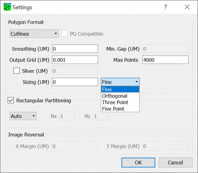
This button opens a dialog that controls certain parameters affecting the Boolean operation.

Polygon Format

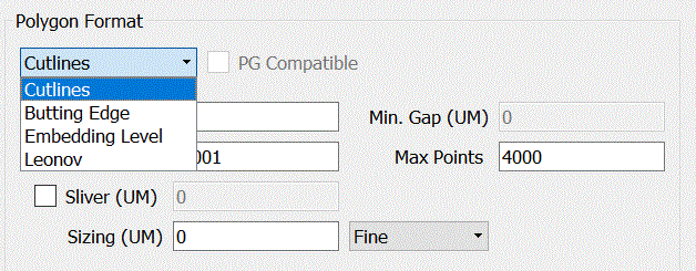
When polygons have "holes", "islands" or "cutouts" there are a number of ways to represent this information since GDSII has no concept of holes inside of boundaries.
Cut Lines - a "cut line" runs from the outer perimeter of the polygon to the inner perimeter and then back out again along the same path.
Butting Edge - the polygon with a hole is sliced into two or more polygons that don't have holes. The edges of the sliced polygons butt up against each other.
Embedding Level - polygons are sorted by layer for each change of polarity.
Leonov - similar to embedding but child polygons belong to a parent.
Most downstream GDSII applications don't understand Embedding Level or Leonov so only use those options when you know your target understands the meaning of the sub layers.
PG Compatible - if checked, makes the output polygons compatible with a pattern generator (which uses two pairs of shutter blades mounted on a rotating head - essentially can print rotated rectangles. This output avoids acute angles.)
Smoothing - this value in UM directs the program to remove vertices whose distance is closer than the parameter. Take care when using smoothing because it may effect slightly the size/area of the boundary.
Min Gap - this value, in um, limits how close a slice (see butting edge) can come to the edge of the polygon.
Output Grid - the grid of the output file. For example, for GDSII files in units of UM, the typical output grid = 0.001. However for GDSII files in units of MM, the output grid would more likely be 0.000001.
Max Points - When GDSII was originally specified the maximum number of vertices per boundary = 255. However this was an arbitrary limit and most tools support much higher number of vertices per boundary (and per path). Set the limit here and the program will insure that no output boundaries will exceed the value. The maximum is 8191 which is determined by the boundary record size.
Sliver - Due to numerical noise and arc approximation small slivers of "metal" may be generated in the Boolean output. To remove these, specify a value for sliver. Details here.
Sizing - Polygons may be sized up or down. Sizing is performed after unionization. Sizing values are typically smaller than the smallest edge of any polygon in the set or unexpected results may occur.
There are different algorithms available on how to deal with the corners of polygons. These are:
Orthogonal - use when all polygons are Manhattan (i.e. the edges are in the X or Y axis)
Three Point - to prevent acute angles from jutting out, approximate the acute angle as an arc using 3 points.
Five Point - to prevent acute angles from jutting out, approximate the acute angle using 5 points.