
The Gerber language basically has two types of commands: Draws, which drag a round or square aperture from point to point; Flashes, which image a special shape at one location. Depending on what you need to do with the DXF file, GBR2DXF can create different entities in DXF.
Draws The program can translate each draw into a polyline whose width matches the draw diameter. For CAD systems that do not support a line width properly the program can output the draw using zero width polyline to outline the area covered by the circuit trace.
Flashes flashes are translated as blocks. The GBR2DXF program defines a block for each aperture definition. It then inserts each block at the same coordinates where the corresponding flash was placed. An option is available that flattens these blocks.
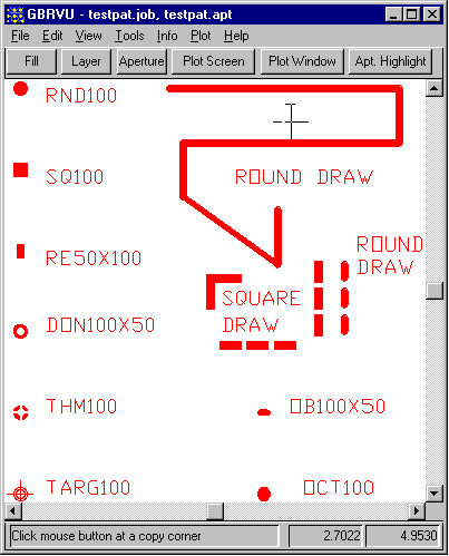
At right you can see the Gerber file we are starting with. It includes basic draws and a collection of fairly standard flash shapes.
Download testpat.gbr.zipif you want to try it yourself. [RS274X Gerber File 8KB]
We will use gbr2dxf to convert this file and we will examine different conversion options below.

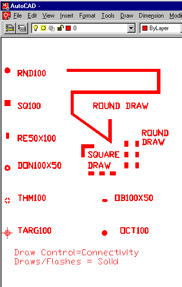
In this example we use the connectivity option for draws and the solid option for flashes.

Polyline endpoints are not compensated to take into account the finite draw aperture width. Also note how AutoCAD does not miter polyline bends. This option produces the smallest DXF output file.
Download result1.dxf [43.9KB].

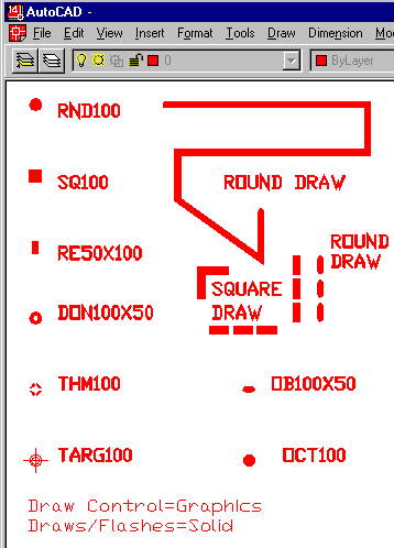
In this example we use the Graphics option for draws and the Solid option for flashes. This gives a better approximation, at least graphically, of the Gerber data.

Polyline endpoints are made to appear round by using a solid donut. The DXF file is larger because additional donuts are placed at the ends of each polyline.
Download result2.dxf [97.7KB].
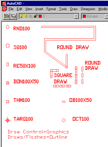
In this example we use the Graphics option for draws and the Outline option for draw/flashes. This is often used for import to CAD tools that don't support polyline width.

In graphics/outline mode the translator creates boundaries of the draws. This mode is useful for programs that do not properly support polylines with width.
Download result3.dxf [87.1KB].
