

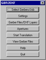
The opening menu takes you through the translation process by clicking on each button from top to bottom. This makes it easy for even occasional users to follow the required steps.
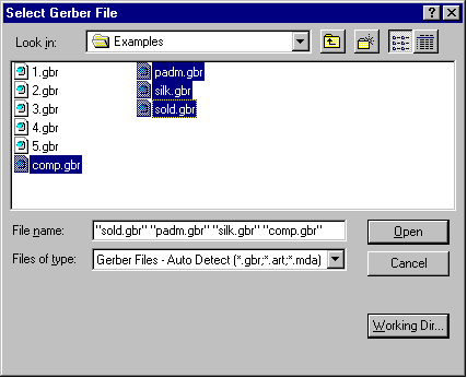
Use this dialog to select your Gerber file or files.
You can select multiple files
easily by holding down the Ctrl or Shift key as you would in Windows Explorer.
You can also configure the program to display files with your choice of suffix such
as .gbr, .ger, .pho or .art through the Preferences menu.
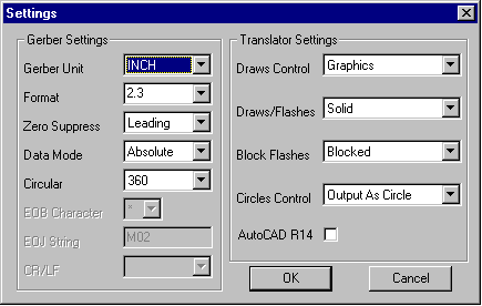
This dialog enables you to set the Gerber parameters and translation settings. GBR2DXF stores these parameters in the aperture file so that if you use the same aperture file from job to job, you don't need to re-enter them. If you have imported an RS274X file these settings are obtained by scanning the file header.
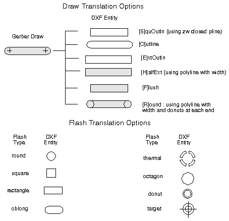
Gerber Draws - The program can translate each draw into an outline using AutoCAD's polyline with width. For CAD systems that do not read in this DXF entity the program can output the draw using zero width polyline to outline the area covered by the circuit trace.
Gerber Flashes - flashes are translated as blocks. The GBR2DXF program creates a block for each aperture definition. It also creates the block definition automatically.
Many CAD programs such as ProEngineer and SolidWorks do not support AutoCAD's polylines - i.e. lines with width. If you translate a Gerber file to DXF and use the DXF polyline width to represent the Gerber draw, ProEngineer will ignore the width and show only the center lines. In order to get a more realistic representation of the board into ProEngineer, we offer a special outline option - instead of using the polyline with width, we can output a zero width polyline that surrounds the area to be imaged. The illustrations below show how this works:

The Gerber data as it appears on your CAM station.
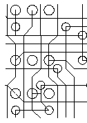
What you would see in ProE or SolidWorks if you use polylines with width.
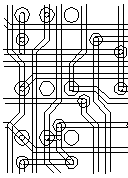
What you see when using GBR2DXF's OUTLINE Option.
If you have RS247X data the apertures are embedded into the file and you can skip this dialog. However the older RS274D Gerber spec does not include the aperture definitions in the Gerber file. These apertures are defined separately and transmitted either in a separate file or on paper. If you are going to convert RS274D files you need to have the apertures on hand so that you can enter them into the dialog box.
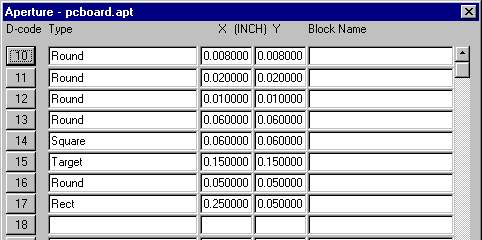
Unfortunately there is no standard format for describing the apertures (that's why RS274X was invented!). However for several popular formats we have developed an aperture translator that automatically imports the aperture description. See APTGENwhich ships with GBR2DXF.