No IC package gets built without a bond wire drawing for the factory. Generating and checking this drawing is often a bottleneck in the package manufacturing process.
Artwork has developed the Wirebond program to speed up and simplify the generation of bond wire documentation.
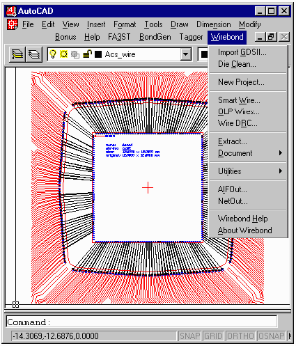
Wirebond has been designed specifically to produce an AutoCAD drawing using as input the AutoCAD drawing of the package shell and die information.
The die information can originate as GDSII stream, AutoCAD, an ascii table or spreadsheet.

When you use Wirebond to create your bond documents you are actually creating an intelligent database inside of the AutoCAD drawing - not just a picture.
This means that the netlist can be reverse extracted from the bondwire drawing, wires can be checked automatically and modifications are much faster and cleaner.

Wirebond can automatically place the downbonds to a paddle or ring area. Downbonds can be directly specified die pad by die pad or can be specified as a function of the die pad netname.
Wirebond sorts out wires and segregates each “tier” onto its own AutoCAD layer. This is required for OLP compatibility.
Wirebond checks the spacing, length and angle of every wire against the design rules. Errors are flagged for review.